Removing a Part of a Continuous Sheet of Charge
1.8: Method of Images
- Page ID
- 17335
A Familiar-Looking Field
We are interested in seeing how the presence of a conductor affects the electric field, so we begin with the simplest case – a point charge near an infinite conducting plane. The key property of the conductor is that the field must strike it at right angles, which means that with a nearby point charge the field must look like:
Figure 1.8.1 – Field of a Point Charge Near a Flat Conductor
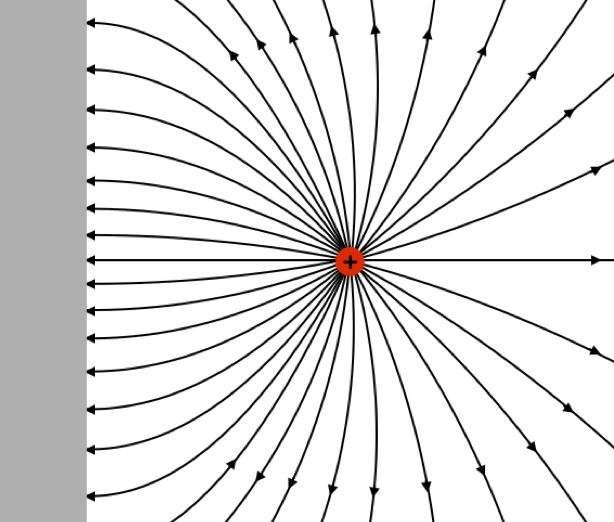
This field actually looks very much like (half of) a field that we have seen before:
Figure 1.8.2 – Field of Point Charge + Flat Conductor = Half a Dipole Field
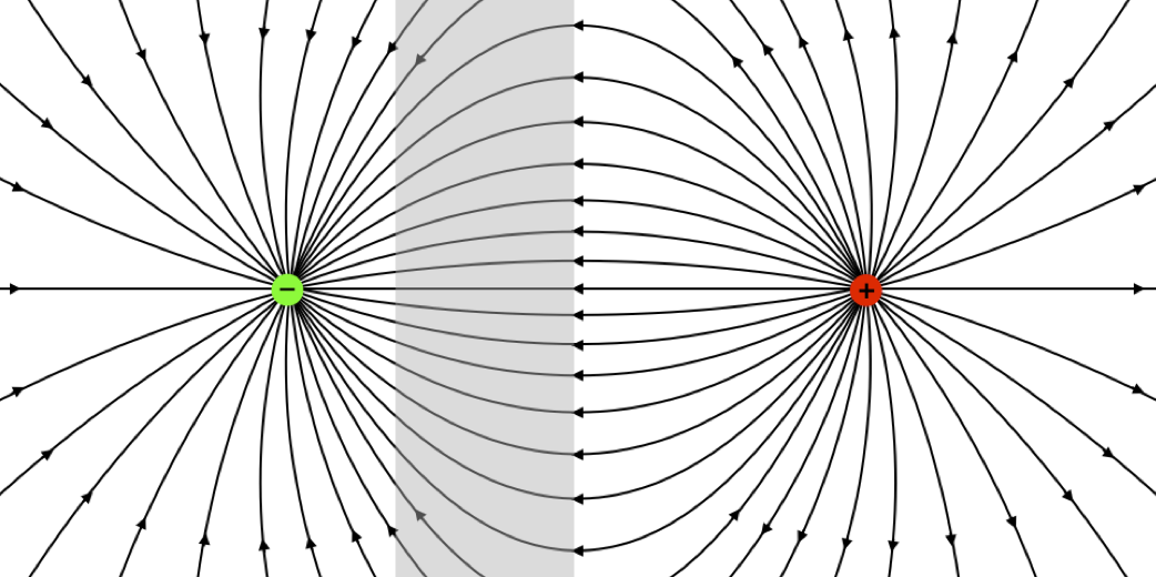
It turns out that this is more than a resemblance of fields. In the region outside the conductor, the field is precisely the same as if the conductor were removed and a second point charge of equal magnitude and opposite sign was symmetrically-placed on the opposite side of where the conducting surface was.
A Clever Trick
The equivalence of these two fields provides us with an opportunity to use a clever trick for analyzing physical situations involving electric charges near flat conductors. For a point charge, this trick involves introducing an imaginary image charge reflected across the conducting surface, and using that charge to derive the actual field outside the conductor surface.
Alert
It can't be stressed enough that this trick does not involve introducing an actual physical charge, any more than constructing a gaussian surface involved constructing an actual physical surface. These are techniques for performing calculations, and one should always keep in mind what the actual physical circumstances are.
Now one might ask, "What's the big deal? All this trick gets us is the field strength for this single situation?" No, we get much more than this. First, consider that the charge outside the conductor will feel a force thanks to this field, and we can actually calculate what this force is, because it is the same as if the charge was in the presence of another point charge. If the charge is a perpendicular distance of \(x\) from the conductor, then the force the conductor exerts on the point charge is:
\[ F = \dfrac{q^2}{4\pi\epsilon_o\left(2x\right)^2} = \dfrac{q^2}{16\pi\epsilon_ox^2} \]
Note that the force is attractive, and it would be attractive if the charge was negative as well, because the image charge is always the opposite sign of the actual charge. Also note that the force on this charge is exerted by the conductor (not by the image charge, which isn't actually there), so by Newton's third law, the force on the conductor is equal and opposite to the force on the point charge.
The power of this trick goes beyond what we can say about a single point charge. As we saw when we integrated fields for charge distributions, we can use superposition to determine a field of many point charges. If several point charges (or a continuous distribution of charge) is located near a flat conductor, then simply introducing an image charge for every charge (whether it is an individual point charge or an infinitesimal chunk of charge from a distribution) will work as a substitute for the conductor.
Charge on the Conductor
Let's return to the case of a point charge near the conducting plane. We know it is attracted to the conductor, but if the image charge isn't really there, what exactly is exerting this force? The answer must be charge, of course, but the conductor is neutrally-charged. But this charge is free to move, so naturally charge of the opposite sign as the point charge will migrate to the surface closest to the point charge, while charge of the opposite sign migrates the opposite direction. The pull of the closer charge is then greater than the push of the more distant charge, causing a net attractive force.
We can ask what the distribution of the charge on the conductor is, and one might be tempted to think that it is evenly-distributed, but this is not the case. We know that the charge density on the surface of a conductor is related to the field there by Equation 1.7.4, and we can use the image charge to determine the field at all positions on the conductor. Clearly the strength of the electric field at the surface has a circular symmetry, meaning that if we draw a line perpendicular to the conducting plane and through the charge, then the field at the surface is the same at all points equidistant from that line. Using the field of the real and image charge and Equation 1.7.4, we can therefore compute the charge density on the conductor as a function of \(r\), the distance from the perpendicular line through the charge. Defining the distance separating the conductor and the charge to be \(a\), we get the following diagram:
Figure 1.8.3 – Computing the Charge Density on the Conductor
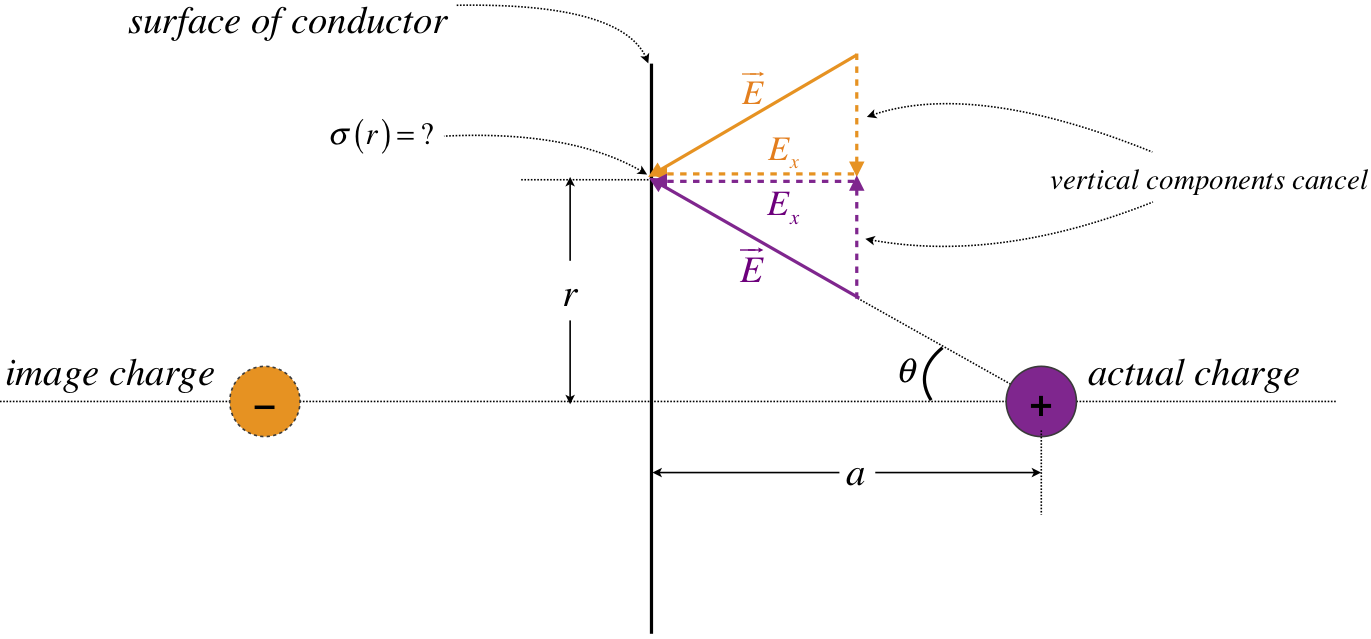
The net electric field at the surface of the conductor is a sum of the \(x\)-components of the fields of the real and image charges, while the \(y\)-components of those fields cancel. The electric field magnitude for each charge comes from the coulomb field. Putting this all together gives:
\[E=2E_x=2E\cos\theta=2\left[\dfrac{Q}{4\pi\epsilon_o \left(r^2+a^2\right)}\right] \left[\dfrac{a}{\sqrt{r^2+a^2}}\right] \;\;\; \Rightarrow \;\;\; \sigma\left(r\right) = \epsilon_o E\left(r\right) = \dfrac{-Qa}{2\pi \left(r^2+a^2\right)^{\frac{3}{2}}} \]
The minus sign was added to account for the fact that the sign of the charge on the surface is opposite the sign of the point charge \(Q\). We can even determine how much total charge is brought to the near surface of the conductor. We get this by integrating the surface charge over the whole surface:
\[charge\;on\;surface=\int\limits_{whole\\surface} \sigma dA \]
This has radial symmetry, so we use polar coordinates. An element of area is \(dA=rdrd\theta\), so:
\[charge\;on\;surface=\int\limits_0^{2\pi}d\theta \int\limits_0^\infty \sigma\left(r\right) rdr = -Qa\int\limits_0^\infty \dfrac{r}{\left(r^2+a^2\right)^{\frac{3}{2}}}dr = -Qa\left[-\left(r^2+a^2\right)^{-\frac{1}{2}}\right]_0^\infty = -Qa\left[\dfrac{1}{a}\right] = -Q\]
So the amount of charge attracted to the near surface is exactly the negative of the point charge! There is actually a very clever alternative means of showing this that doesn't involve an integral, using Gauss's law. Construct a half-spherical gaussian surface of infinite radius with the flat part within the metal of the conducting plane, as depicted below.
Figure 1.8.4 – Gaussian Surface for Point Charge and Conducting Plane
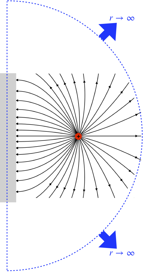
The flat part of this gaussian surface permits zero flux, since the electric field inside the conductor vanishes, but what about the curved part of the gaussian surface? Well, the angles between the electric field lines and the surface vary wildly from one point on the hemisphere to another, but what about the magnitude of the electric field? This field is precisely the same as that of a dipole, which we already know from Equation 1.4.10 weakens with an inverse-cube law far from the source:
\[E_{large\;r}\propto \dfrac{1}{r^3} \]
The area of this hemisphere grows with the square of the radius:
\[A_{large\;r}\propto r^2 \]
The flux through any little part of the surface is no larger than the product of the magnitude of the electric field and the area (it is smaller when the angle the field makes with the area vector is greater than zero), so total flux changes with \(r\) no faster than:
\[\Phi_E\left(curved\;surface\right) \le EA \propto \dfrac{r^2}{r^3} = \dfrac{1}{r} \]
But as we are letting \(r\rightarrow\infty\), this flux goes to zero, which when added to the zero flux through the flat surface, means that the total flux though this surface is zero. Gauss's law therefore insists that the enclosed charge is zero. The point charge contributes \(Q\) to the interior, which means that the conducting surface (also enclosed by the gaussian surface) must contribute \(-Q\).
Field on the Other Side of the Conductor
We know that the image charge is a fabrication of our imaginations, but what actually is happening on the other side of this conductor? There is clearly \(Q\) on the far side, left behind by the \(-Q\) that migrated to the near side (the conductor is neutrally-charged overall), so what kind of field does this create? Let's start by confirming that the field inside the conductor vanishes as it should.
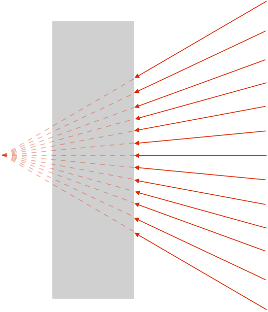
Begin by considering what the field of just the charges on the near surface of the conductor looks like outside that surface. We know that these charges create a field that (in that region) looks identical to the field created by the image charge, so it looks like:
Figure 1.8.5a – Field of the Surface Charge Alone
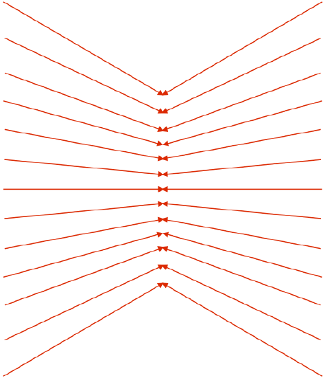
Next imagine removing the conductor, but leaving the surface charge fixed in place. Then the field would look the same on both sides of the charge:
Figure 1.8.5b – Field of the Surface Charge Alone
And now into this field, let's place our real positive charge in its proper position. Since the field lines on the right side of the figure above converge to the position of the image charge, by symmetry the field lines on the left side must converge to the position of the real charge. This means that the field on the left side above cancels the real point charge field in that region, giving a total field of zero to the left, and (as we have already shown) the half-dipole field to the right:
Figure 1.8.6 – Superposition of Real Charge's Field with Surface Charge's Field
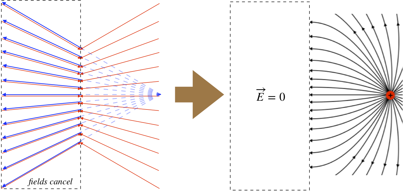
So the charges are distributed on the surface of the conductor such that their field cancels the field of the point charge everywhere to the left of the surface. This confirms one thing we already know, which is that the field within the metal is zero. But it also proves that the charge left on the other side of the conductor is not affected at all by the fields of the point charge or the other surface charge. These orphaned charges will only be affected by one another, and will therefore repel each other the best they can. this leads to a uniform distribution on the other side of the conducting plane. When the charge density is uniform, it is simply the total charge divided by the total area. But the total charge is finite (it equals \(Q\)), while the area is infinite, so the surface charge density on the other side of the conductor is zero, and since the field at the surface is proportional to the surface charge density, the electric field is also zero! It is interesting that there is the same amount of charge on both sides of the conductor, and it results in a field on one side, and no field on the other, where it is simply spread too thin.
Applications
It should be apparent from the discussion above that the trick of using image charges (known as the method of images ) has many applications for determining fields, forces, and surface charge densities. Specifically, we do not have to limit ourselves to the case of a single point charge. If there are multiple point charges present, we simply have to construct an image charge for each of them and use superposition. This can then be extended to continuous collections of charge as well – just construct an image collection of charge and use superposition from there.
For this class, we will limit ourselves to the simplest geometry of a single plane conductor, but the method can be expanded to multiple conducting planes and even spherical conductors.
Example \(\PageIndex{1}\)
A thin circular plastic ring carries a net charge that is uniformly distributed throughout the ring with a linear density of \(\lambda\). This ring is positioned parallel to a neutrally-charged infinite conducting plane such that its distance from the plane equals the radius of the ring.
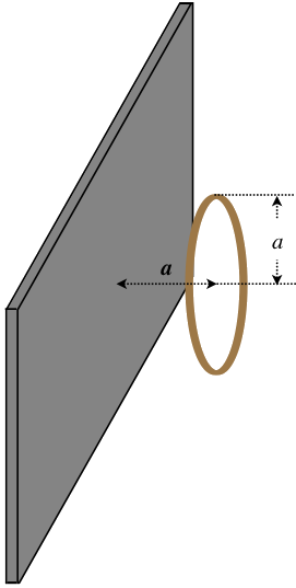
In Example 1.3.1, we showed that the magnitude of the electric field on the axis of such a ring is given by:
\[E\left(x\right) = \dfrac{\lambda a x}{2\epsilon_o\left(a^2+x^2\right)^\frac{3}{2}}, \nonumber\]
where \(x\) is the distance from the ring along the axis. The field points along the axis of the ring, toward the ring (if the charge is negative), or away from it (if the charge is positive). A charged point particle is placed at the center of the ring. This particle has the same total charge as the ring, but it has the opposite sign. Find the magnitude and direction of the net force on this particle in terms of \(\lambda\).
- Solution
-
We can use the method of images to replace the conductor with image charges placed symmetrically on the opposite side of the conducting surface. We need images for both the point charge and the ring. The plastic ring will not contribute to the force on the point particle, because the particle is at its center, where the electric field of the ring vanishes. So the only two contributors to the force are the image point charge and the image ring. Start by determining the amount of charge on the particle in terms of the given linear density:
\[Q=\lambda l = 2\pi a \;\lambda\nonumber\]
The force between the point particle and its image is just the Coulomb force (with a separation of \(r=2a\)), and it is attractive (toward the plane), since the image charge has the opposite sign:
\[F_1= \dfrac{Q^2}{4\pi\epsilon_o \left(2a\right)^2} = \dfrac{\pi\lambda^2}{4\epsilon_o} \nonumber\]
The force on the point charge by the image ring is the product of \(Q\) and the field of the image ring, and it is repulsive (the charge in the image ring has the opposite sign of the real ring, which is the same sign as the point charge). The image ring is a distance \(x=2a\) from the point charge, so:
\[F_2= QE_{image\;ring} = \left(2\pi a\; \lambda\right)\dfrac{\lambda a \left(2a\right)}{2\epsilon_o \left(a^2+\left(2a\right)^2\right)^\frac{3}{2}} = \dfrac{2\pi\lambda^2}{5\sqrt{5} \epsilon_o} \nonumber\]
These forces are in opposite directions, so the net force on the point charge is:
\[F=F_1-F_2=\boxed{\left(\dfrac{1}{4}-\dfrac{2}{5\sqrt{5}}\right)\dfrac{\pi\lambda^2}{\epsilon_o}} \nonumber\]
The fact that this number is positive means that \(F_1>F_2\), so the net force is toward the conductor.
Source: https://phys.libretexts.org/Courses/University_of_California_Davis/UCD%3A_Physics_9C__Electricity_and_Magnetism/1%3A_Electrostatic_Fields/1.8%3A_Method_of_Images